How Does an Acoustic Camera Work?
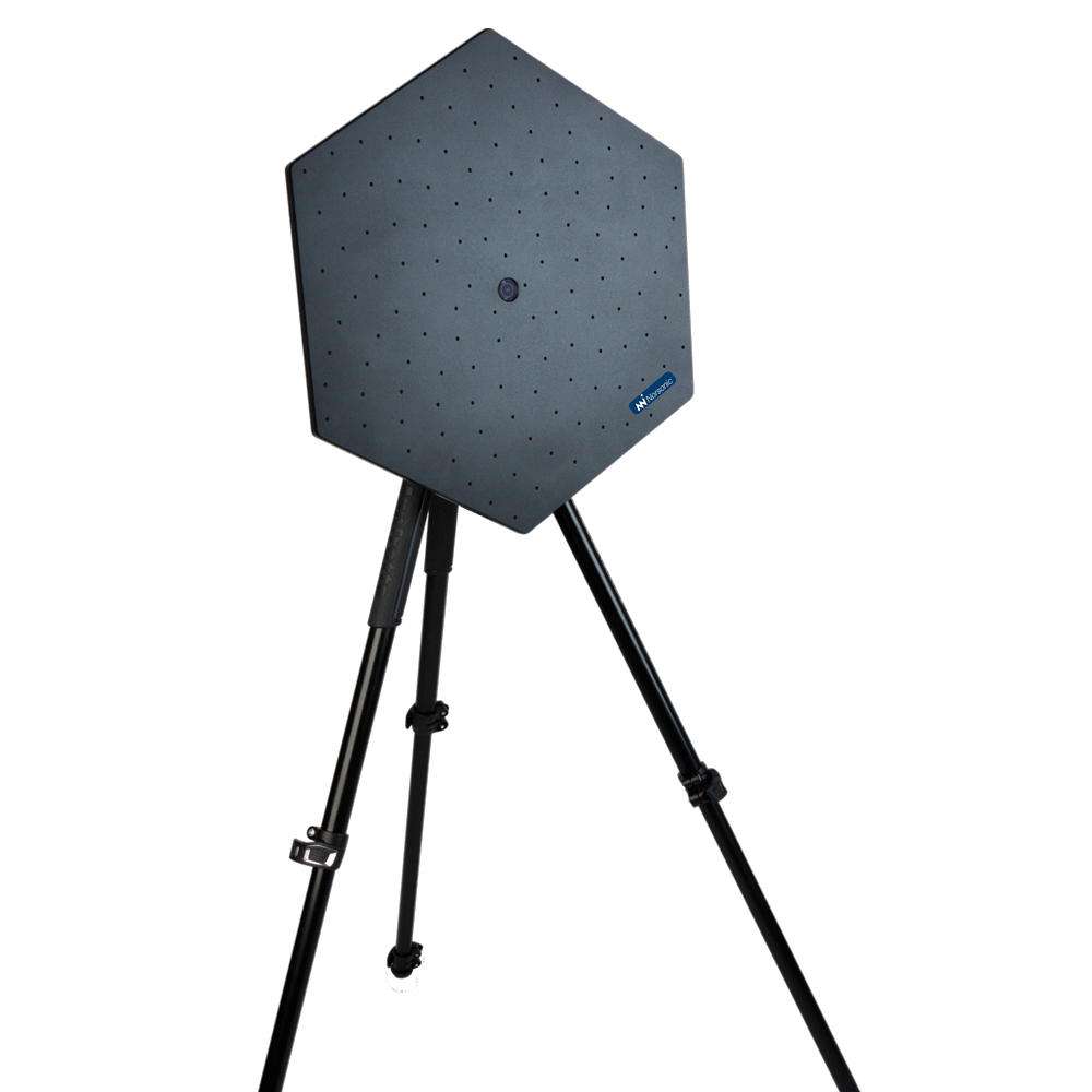
An acoustic camera combines a microphone array with a video camera to visualize sound sources in real-time. It uses beamforming algorithms to calculate sound direction and intensity.
Beamforming
The core signal processing algorithm that uses time delays between microphones to calculate sound direction and intensity. More microphones provide higher spatial resolution.
3D Visualization
Real-time overlay of sound map on video image. Different colors represent different sound levels for quick source identification.
Modular Design
Hextile/Multitile system allows configuration from 128 to 384 microphones based on application requirements.
Real-Time Processing
Built-in processor for instant visualization of results. No post-processing needed for quick diagnostics.
Key Parameters
Understanding these parameters helps you select the right configuration for your application.
Spatial Resolution
Angular Resolution
Ability to distinguish between close sound sources. Depends on array size, frequency, and distance.
Dynamic Range
Source Level Separation
Difference between highest and lowest sound levels that can be measured. Larger with more microphones.
Frequency Range
Measurable Frequencies
Range of frequencies that can be measured. Lower limit depends on array size, upper on microphone spacing.
Measurement Distance
Source Distance
Distance from array to source. Larger distances require larger arrays for same resolution.
Field of View
Angular Coverage
Angle that the camera can measure. Determined by video camera lens.
Frame Rate
Update Speed
Number of sound maps calculated per second. Faster for capturing moving sources.
Array Configurations
The modular Nor848B system allows different configurations based on application requirements.
Entry-level configuration for general applications. Portable and easy to set up.
- Machinery diagnostics
- Air leak detection
- Quality inspection
High spatial resolution for advanced applications and larger distances.
- Automotive NVH
- Building facades
- Wind turbines
Custom design for specific requirements. Consult our engineers.
- R&D
- Aircraft testing
- Special applications
Applications
Acoustic cameras have broad applications in industry, automotive, construction, and research.
Automotive NVH
Identify noise sources in engines, transmissions, and exhaust systems. Pass-by testing per ISO 362. Interior and wind noise analysis.
Industrial Machinery
Quick diagnostics of noise sources on production equipment. Identify worn bearings and damaged parts. Plan mitigation measures.
Wind Turbines
Identify blade noise and mechanical sources. Optimize maintenance and planning. Remote measurements with large arrays.
Building Facades
Identify sound transmission paths through windows and walls. Quality inspection of installations. Noise complaint investigation.
HVAC Systems
Locate noise sources in fans, ducts, and dampers. Optimize design for noise reduction.
Quality Control
Production line noise screening for defect detection. Product comparison. Automated quality assurance.
Measurement Procedures
Follow these steps to obtain accurate results with the acoustic camera.
- 1Select appropriate configuration (number of Hextiles) based on application and distance
- 2Mount array on tripod or mounting structure
- 3Connect array to processing unit via USB cable
- 4Calibrate system (field calibration or verification)
- 5Adjust camera angle to cover measurement area
- 1Select appropriate frequency range for application
- 2Set focus distance (distance from array to source)
- 3Start recording or live viewing
- 4Analyze sound map to identify dominant sources
- 5Use cursors to determine sound levels at specific locations
- 1Export sound maps as images or video
- 2Use spectral analysis functions for detailed investigation
- 3Compare before/after measurements to evaluate improvements
- 4Create reports with sound maps and quantitative data
- 5Archive data for future reference